COMMUNICATION PROTOCOLS
A ¡°communication protocol¡± is a means by which data is exchanged between the vehicle¡¯s on-board computer and an external data retrieval device, such as a Code Reader or Scan Tool. The SAE has defined three distinct communication protocol ¡°classifications,¡± based on the speed at which data transfer takes place:
- Class A ¨C Supports data transfer speed of up to 10Kb/s
- Class B ¨C Supports data transfer speeds of up to 100Kb/s
- Class C ¨C Supports data transfer speeds of up to 1Mb/s
Currently, five communication protocols are defined for use in OBD2 computer control systems. An OBD2-compliant vehicle will employ one of the following protocols:
- ISO 9141-2
- SAE J1850 (VPW 10.4K)
- SAE J1850 (PWM 41.6K)
- ISO 14230-4 KW 2000
- ISO 15765 CAN (Control Area Network)
ISO 9141-2
Classification: A
Commonly Used On: European, Asian, and some Chrysler
Description:
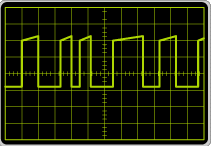
The ISO 9141-2 protocol is essentially a serial interface, similar to the RS232 interface found in personal computers. The ISO 9141-2 data bus can be implemented as either a single-wire or two-wire interface (DLC pins 7 and 15) with a data transfer speed of up to 10.4 Kb/s. The ¡°K¡± line (pin 7) is a bidirectional line. During initialization, this line carries address information or (in the case of fast initialization), the ¡°wake up¡± pattern from the Code Reader or Scan Tool to the vehicle¡¯s computer. After initialization, bidirectional data flow between the Code Reader or Scan Tool and the vehicle¡¯s computer takes place over the ¡°K¡± line. The ¡°L¡± line (pin 15) is a unidirectional line (from the Code Reader or Scan Tool to the vehicle¡¯s computer). It is used only during initialization to carry address information or (in the case of fast initialization), the ¡°wake up¡± pattern from the Code Reader or Scan Tool to the vehicle¡¯s computer simultaneously with the ¡°K¡± line. After initialization, the ¡°L¡± line is held in a ¡°high¡± (logic ¡°1¡±) state.
The ISO 9141-2 data signal is a square wave of uniform frequency, with a varying voltage level (either +12VDC or 0VDC), as illustrated.
ISO 14230-4 KW 2000
Classification: A
Commonly Used On: European, Asian, and some Chrysler
Description:
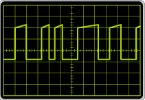
The ISO 14230-4 KW 2000 protocol is a variation of the ISO 9141-2 protocol, complying with the specific requirements of ISO 14230-2 and ISO 14230 Parts 2 and 3. The ISO ISO 14230-4 data bus can be implemented as either a single-wire or two-wire interface (DLC pins 7 and 15) with a data transfer speed of up to 10.4 Kb/s. The ¡°K¡± line (pin 7) is a bidirectional line. During initialization, this line carries address information or (in the case of fast initialization), the ¡°wake up¡± pattern from the Code Reader or Scan Tool to the vehicle¡¯s computer. After initialization, bidirectional data flow between the Code Reader or Scan Tool and the vehicle¡¯s computer takes place over the ¡°K¡± line. The ¡°L¡± line (pin 15) is a unidirectional line (from the Code Reader or Scan Tool to the vehicle¡¯s computer). It is used only during initialization to carry address information or (in the case of fast initialization), the ¡°wake up¡± pattern from the Code Reader or Scan Tool to the vehicle¡¯s computer simultaneously with the ¡°K¡± line. After initialization, the ¡°L¡± line is held in a ¡°high¡± (logic ¡°1¡±) state.
The ISO 14230-4 KW 2000 data signal is a square wave of uniform frequency, with a varying voltage level (either +12VDC or 0VDC), as illustrated.
SAE J1850 (VPW 10.4K)
Classification: B
Commonly Used On: Chrysler and General Motors
Description:
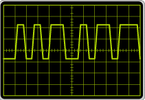
The SAE J1850 (VPW 10.4K) data bus is implemented as a single-wire bidirectional interface (DLC pin 2), with a data transfer speed of 10.4 Kb/s. The data signal is a series of pulses of uniform amplitude (7VDC) and variable pulse width (VPW), as illustrated.
SAE J1850 (PWM 41.6K)
Classification: B
Commonly Used On: Ford
Description:
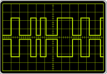
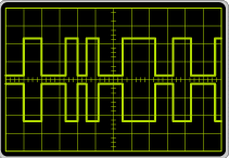
The SAE J1850 (PWM 41.6K) protocol is implemented as a two-wire bidirectional interface (DLC pins 2 and 10) that supports data transfer rates of up to 41.6 Kb/s. The ¡°+¡± (pin 2) and ¡°-¡° (pin 10) bus lines carry differential signals; that is, the signal on the ¡°-¡° line is an exact inversion of the signal on the ¡°+¡± line. This implementation minimizes the effects of Radio Frequency Interference (RFI) or Electromagnetic Interference (EMI) on the data signal.
The SAE J1850 (PWM 41.6K) data signal is a series of differential pulses of uniform amplitude (+5VDC, -5VDC) and modulated pulse width (PWM), as illustrated.
ISO 15765 CAN (Control Area Network)
Classification: C
Commonly Used On: Beginning in 2008, all new vehicles will be required to use the CAN protocol
Description:
The ISO 15765 CAN protocol is implemented as a two-wire bidirectional interface (DLC pins 6 and 14) that supports data transfer rates of up to 1 Mb/s. The ¡°High¡± (pin 6) and ¡°Low¡° (pin 14) bus lines carry differential signals; that is, the signal on the ¡°Low¡° line is an exact inversion of the signal on the ¡°High¡± line. This implementation minimizes the effects of Radio Frequency Interference (RFI) or Electromagnetic Interference (EMI) on the data signal.
The ISO 15765 CAN data signal is a series of differential pulses of uniform amplitude (+5VDC, -5VDC) and modulated pulse width (PWM), as illustrated.
